hyperCube

Cubes in all Dimensions

Frank Sottile
Cubes are among the easiest regular polytopes to describe, and there are cubes of every dimension:
The cube in dimension d is simply the Cartesian product of d intervals, [0,1]d.
The aim of this activity is to study cubes (e.g. make sense of this definition) and to build a projection of
a four-dimensional cube into the 3-dimensional space that we inhabit, both to better understand cubes, and to
better understand four and perhaps higher dimensions.

Cubes
It is best to start small.
In dimension d=0, the cube [0,1]0 is simply a point, .
A cube in dimension d=1 is the interval [0,1]. It has two endpoints (its vertices). Perhaps it is better to discuss how to construct the 1-cube from the 0-cube. Start with the 0-cube, and put a copy of it one unit away from the first (giving two vertices). The join the two vertices to get the interval [0,1]. This is on the left below.
A two-dimensional cube is a square. To construct it, begin with a cube in dimension one. Duplicate it, and move the copy one unit in a new direction.
For each vertex in the original, put in an edge between that vertex and its copy (as in the previous step). Also put in a square (a 2-face) between the original edge and its copy. (You might begin to see the recursion in this construction.) This is second from the left below.
A three-dimensional cube is a cube. To construct it, begin with a cube in dimension two. Duplicate it, and move the copy one unit in a new direction.
For each vertex in the original, put in an edge between that vertex and its copy. For each edge in the original, put in a square between that edge and its copy. Also put in a cube (a 3-face) between the original square and its copy. (You surely can now see the recursion in this construction.) This is second from the right above.
This becomes a bit harder in higher dimensions, as we are constrained to live in three-dimensions. There is not a new fourth direction to move in, so we must make do with some representation of the four-dimensional cube (and even more so in higher dimensions!) One common representation is a Schlegel diagram of the four-dimensional cube, which is depicted in above on the right.

Oblique view (projections)
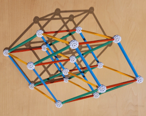
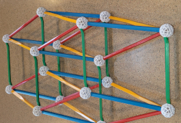
Our construction will not be the Schlegel diagram above, but rather a projection of the four-dimensional cube into 3-dimensional space.
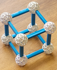
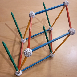
To begin, consider the cube above, which is viewed at an angle so that we may appreciate all eight of its vertices and twelve of its edges. Note that the edges come in three sets of four parallel edges. Note also that none of the six square facets of cube appears square (but the square next to it appears square). That is because we are seeing a projection of the cube to two-dimensional space. Because the center of projection is the camera lens rather than a point at infinity, there is some distortion, but there are three pairs of parallel faces, with each pair consisting of isomorphic (congruent) parallelograms.

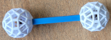
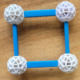
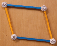
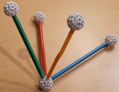
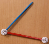
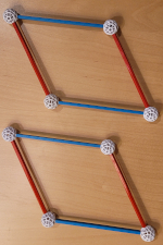
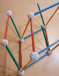
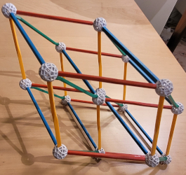
At the left below is a parallelogram, which is determined by the two lengths of the edges and their relative angle.

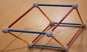
To make a 3-dimensional parallelipiped, you choose three directions for the three edges, then build each pair out to parallelograms, and then complete into the full figure. 
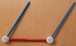
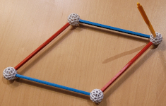
One is displayed second from the left below. For this, we began with the rightmost zome, choose three edges (yellow, blue, and red struts) coming from it, and then built it out.

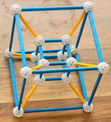
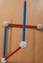
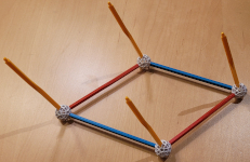
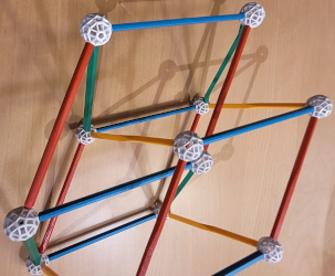
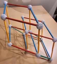
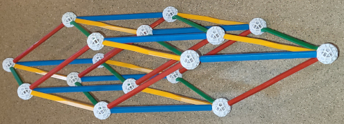
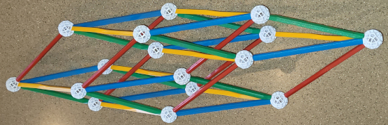
For the four-dimensional cube, we will pick four directions from a vertex and then similarly "build it out" (but not quite, see the instructions below.) 
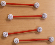
This is the image of each of the four unit intervals (along each of the four coordinate axes) in R4 under the projection map R4-->R3 sending the four-cube to the model. 
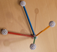
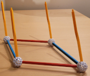
We show this local configuration below at right. 
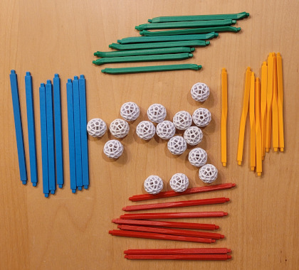
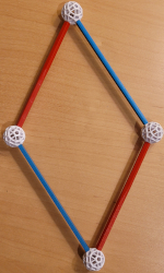
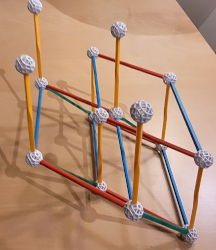
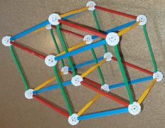
When you build your model below, there are three places where you make a choice of a direction for a new strut (blue, yellow, green). Almost every choice is valid, and they each give a slightly different projection. (Your model likely will not look exactly as mine does.)
 

Building a projection of the four-cube into three-dimensional space
  First, empty out your bag of zometools. You should have at least 16 balls, and eight each of red, blue, yellow, and green struts, which is shown at right. I put extra into each bag in case of loss. Because the balls roll and all are choking hazards, keep them in the bag, in a bowl.
Start by examining one of the balls, called a "zome" (at right). It has 12 pentagonal holes, 20 triangular holes, and 30 rectangular holes. (Do you recognize these numbers from your platonic solids?) Were the rectangles squares, this would be perhaps the most attractive Archimedean solid, the rhombicosidodecahedron. The name rolls off the tongue.
The struts go into the holes (do not put any in, yet).
Examine one strut of each color. Blue struts go into the rectangular holes, yellow struts go into the triangular holes, red struts go into the pentagonal holes, which also take green struts (the green struts are subtle, we will discuss them below).
Take a red strut and push it into a pentagonal hole. You can pull it out with two hands, but that is dangerous if you are disassembling anything more complicated. Instead, grasp the strut in one hand with your fingers on the zome and squeeze your fingers together, while holding the strut. The zome will pop off, safely. (If you pull with both hands, when the strut comes lose, there is a potentially uncontrollable recoil---try it.)
Do this with the other color struts. Blue struts are nearly as robust as red struts, and green are a robust as red---this is due to the size of the peg that fits into the hole. Yellow struts, however, are very delicate, so take care. (They also unfortunately pinch your hand when taking them off in the recommended way.)

Build your model of a four-dimensional cube
I recommend reading this first, and then follow the directions fairly closely; I have done this activity in person over a dozen times, and regularly build models using zometools.
1: Attach eight balls to four red struts, two per strut, creating four one-dimensional cubes.
2: Now comes one of the main steps: On one of your four red 1-dimensional cubes, attach a single blue strut. You may choose any rectangular hole to put it in, but I recommend choosing one so that the red and blue struts form an acute angle. You are free to choose to make a different projection than illustrated here (choosing different holes to put the struts in than I do).
3: In this step, you must attach a blue strut to the other zome, in the same hole as the first one. If you do this successfully, the two blue struts will be parallel. An easy way to test this is if the structure lies flat. If they are not, then pull it out and try again. It helps to pick up your construction and sight along the red bar to see if the two blues are aligned. It may also help to examine both zomes carefully.

4: Now you need to attach one red 1-dimensional cube to the ends of both blue struts. Start with attaching it at one blue strut. Not any rectangular hole will do. You will know it is the correct one if the other ball on the red strut lines up with the other blue strut, and all four bars lie flat. These are precision tools, and you will not need to force/bend/apply torque to anything to make it fit. Above is one incorrect placement (which does not lie flat) and one correct placement, making a parallelogram.
5: Now make a second, identical, parallelogram, using the remaining two red 1-dimensional cubes. This is illustrated on the left below.
6: Now is time for another choice. Select one of your two identical parallelograms. At one vertex (zome), insert one yellow strut in almost any way. Be careful not to stress the yellow strut once it is inserted as its peg may easily break. The only restriction is that the three struts should not be nearly co-planar. As before, I suggest that you choose an acute vertex. One way to do this is illustrated in the second picture on the left below.

7: Insert three other yellow struts into the remaining three zomes, into exactly the same (corresponding) hole. If you choose the correct holes, they will be parallel, and you may sight along the red and blue struts to check this, pairwise. The two pictures on the right above illustrate this. Note that the struts do not appear parallel in the first because of the distortion of the camera.
8: Now attach the second parallelogram to the ends of the four yellow struts. The same rules apply. Once you attach one yellow strut to a zome of the second parallelogram, the model should freely line up the other three yellow struts into the corresponding holes of their zomes, without bending or forcing anything. If you have to force or bend anything, than you erred in your choice of hole for the first yellow strut. This is illustrated below on the left.

9: Now it is time for the green struts. These are very tricky. Each of the other struts is symmetric, if you pull it out of its hole in a zome, rotate it (by 120, 90, or 72 degrees), and reinsert it, the strut looks exactly the same as before. Not so with the greens. The pictures above show four different views of the head of a green strut; notice how the orientation of peg changes. Look closely at one of your green struts to see this. Each green strut has roughly a quadrilateral cross section, except near its head, where a fifth side is cut (this is seen in the first picture, and is on the opposite side of the view in the third). I use this extra fifth side near the head to help me line up and orient the green struts.
10: With that preparation, place your model on a flat surface, and insert on green into a zome; I would recommend putting it into an acute zome or at least point into the model. Make sure that it is not co-planar with the other struts at its zome.
Then place three more into the three remaining zomes on that parallelogram, taking care to put them in the exact same orientation as the first. This placement of the greens is one of the more subtle points of building this model. You can see this below at left.
11: A test if you succeeded in placing the greens is the next step. Put zomes on the end of two greens either above a blue or a red strut. If the greens are parallel, then you may put in a (blue or red) strut between the two zomes that is exactly parallel to the one below it, and there is not twisting or pushing; the holes are lined up just right. If there is any twisting, or if the holes are not lined uo just right, remove the new strut and reinsert it. I show this with a red strut below, second from the left.

12: Following what you now know, complete the parallelogram on top of the four green struts, as shown above second from right.
13: Now you can either put in the remaining four green struts (heeding the advice on them being parallel) or do the same with the remaining four yellow struts (as I did, above at right). I would recommend doing the yellow. Do attach the final four zomes to these struts, as shown.
14: Build another red-blue parallelogram on top of the yellow struts, using these last four zomes. (See below at left.)
15: All that is now needed is to put in the four remaining green struts. All that was discussed about then earlier still applies. I provide you with two views.


Last modified: Sun Apr 23 14:45:15 EDT 2022